This question was one that Mark had never encountered before, which probably means that most of you won't either; however, it's a very good illustration of how InRoads is a 'tool' that can be used to solve problems that it may not have been originally designed to do.
The process Mark shows here simply strings together multiple tools that you are likely familiar with, to produce the desired results. See if you can follow his process . . . and start thinking 'out of the box'.
Hello,
Is there an automated way to take elements that are located along or adjacent to a horizontal alignment and project those elements onto a straightened version of that alignment at their correct station and offset? Can this be done either via MicroStation or some InRoads command? Please refer to the attached plan view and corresponding straight-line diagram example for an illustration of what I'm referring to (hopefully they get the point across).


The only way I've yet found is to manually cut/break the alignment and the adjacent elements at each Point of Intersection (PI), select each PI grouping and rotate them all to be in line with one another. I've racked my brain trying to think of some way to use various InRoads commands to accomplish this same task. Can this be automated either via MicroStation or some InRoads command? If not with either of these, is there some software that can? I appreciate any help on this question.
- Jeb

Here is the Zen Dude's response:
Jeb, that's a really nice problem!
I don't know what your InRoads experience level is, and you might not totally follow this, but here are my thoughts:
In a nutshell, here is what I did:
1) Put those adjacent alignments into the Geometry Project
2) Exported them out as Station / Offset along the mainline stationing
3) Created a new 'straight' alignment that is as long as the mainline alignment
4) Imported the Station / Offset information for the adjacent alignment back into InRoads as Cogo Points using the Text Import Wizard (while having the new 'straight' alignment active)
5) Create new alignments from those imported Cogo Points using the Create / Edit Alignment by Cogo Points
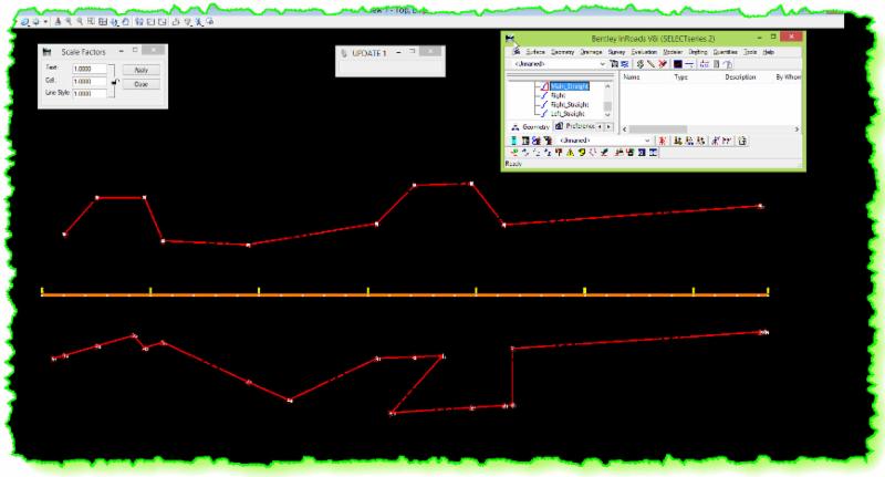
6) My test went from this:

To this:
In playing around with this I documented and captured the entire process with graphics and here it is in more detail:
I started my test creating a Main alignment and then two other alignments. One to the Right and another to the Left. So, you'll need to create alignments from those adjacent elements using Import Geometry from Graphics or some other method. That's pretty easy and straight forward.
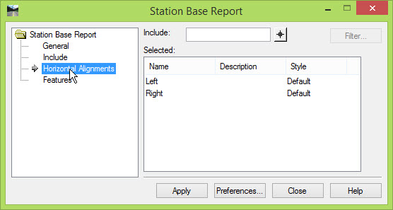
Then I went to InRoads > Tools > XML Reports > Station Base. Set the Main alignment on the General leaf; on the Include leaf toggle on Cardinal Points of Selected Alignments / Features so it picks up the PI's from the adjacent (right and left) alignments. On the Horizontal Alignment leaf add the two (or more) adjacent alignments in there.


When you Apply this, it will report on the PI points of the adjacent alignments. The report style sheet that you select will determine what it reports on and how it is formatted. Picking the StationOffset.xsl formats the extracted information into a Station and Offset listing (among other reported information).

Right-clicking in the right report panel will let you save that information to Excel.

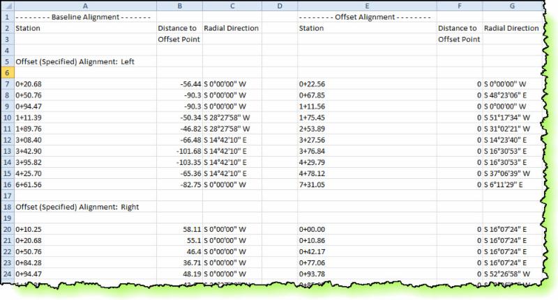
I modified the spreadsheet to only show the Station and Offset.

Save that as a comma delimited file, or just cut and paste the desired columns (Station & Offset) into Notepad.

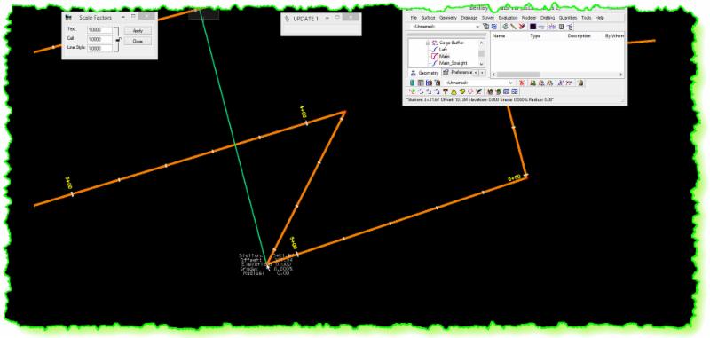
Before you move on, there is a quality control step that you should do, that I'll mention now. When you extract the Station and Offsets, you can graphically verify what you are getting with a little-known trick. When you click Apply on the Station Base Report, you can hold down the Ctrl key and it will also draw a line where it is pulling a Station / Offset. It will look like this:

This is a good way to confirm that you are getting what you want. In doing this, I noticed that if your adjacent alignment goes backward from your mainline stationing, the reporting won't report on it correctly. This is pretty clear when you display the graphical view during reporting. This is what I found doing the right side of my test.

Notice how it doesn't pick up the backward jog on the adjacent alignment? At this point all that I did was verify that all the points that I needed where correctly reported on. You can 'make' InRoads report on that 'jog' correctly, but it's really easy to just tweak your text file or spreadsheet to correct for these little things when they occur. I used the InRoads > Tools > Tracking > Horizontal Alignments tool to determine the correct offset to apply at that station. (Notice that it does report on the station, but it grabs the first offset where it hits the adjacent alignment and doesn't extend itself to the 'back jog point'. Just find that Station and edit the Offset to the correct value.)
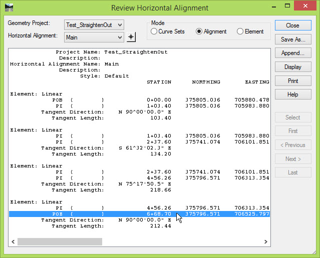
Next, I created a new 'straight' alignment that was as long as the main alignment. I just did a quick report and noted the final stationing. In my case it was 668.70 ft. long.
To create the 'straight' alignment, I created a new Horizontal Alignment placeholder in the Geometry Project and then used the Add Fixed Horizontal Line under the Horizontal Element toolset. I picked an arbitrary starting Point where I wanted to begin my 'straight' alignment in plan view. And then entered the Direction (due East) and the Distance (as long as my main alignment).


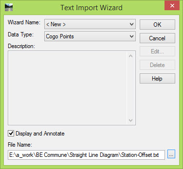
Then import the Station and Offset text file using the Text Import Wizard, with the new 'straight' alignment as active. The Data Type will be Cogo Points. This will place the Station / Offset points into the Geometry Project relative to the new 'straight' alignment. The wizard will walk you through the setup, but the text file only has two columns so it's pretty easy.


My results looked like this:

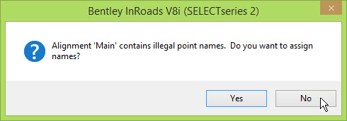
Once the Cogo Points have been imported into the Geometry Project, go to Geometry > Utilities > Create / Edit Alignment by Cogo Points to create the adjacent alignments. If a message pops up asking if you want to assign names, just say No. That pops up because your currently active alignment (the 'straight' main) wasn't created with assigned point Names, and you don't really care about that here.
Enter a new name for one of your adjacent alignments and then hit the Tab key. The imported points should be, more or less, in the correct order so just determine the point range and enter it into the Alignment Definition window. You can also use the Graphical Input and Start and then just pick each point on the MicroStation screen to create the connectivity. Either way, once you are done, just click Apply to create the alignment.

Enter a new Name for any other alignments and then Tab to begin creation of additional adjacent alignments.

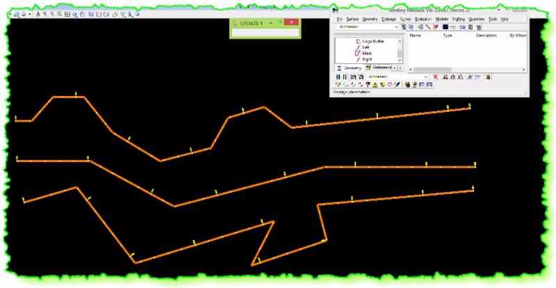
Once I was done it looked like this:

And I think this is pretty close to what you wanted.
Let me know if you have any questions, and good luck!!
Civilly yours,
- zen
 Very knowledgeable in real life experiences. Has used the product for production and not just a teacher. His examples can be related to.


