TECHNICAL TIP ~ InRoads DTM Conflicts, Part 6
THE FINAL WORD ON DTM CONFLICTS
You have no idea how badly I want to put this topic to rest, but there are just a few more things to be said that just can't be ignored.
Okay, first, I've been lying to you all along.
There aren't two types of errors . . . there are more. Sorry, I just didn't know how to break it to you earlier and I wanted to be gentle. Actually what I was always referring to with regards to the "two" earlier errors that I mentioned are the two errors that InRoads "reports" on. There are others that the software doesn't tell you about.
Now, let's move on to something that most InRoads users are not even vaguely aware of; and in fact I have never met anyone who was aware of this. (Please let me know if you knew about this so I don't have to feel so alone ; ) This part of the technical topic isn't so much a 'how-to-do-something-tip' as it is a big 'heads-up'. And if this particular situation arises it can throw you for a loop if you are not aware of this (it sure threw mefor a loop when I first encountered it).
Unbeknownst to you, InRoads could be deleting Random points from your DTM surface without your permission, and without you even knowing. Okay, there, I said it. Now let me expound on this.
Think back to all of the previous content that I've been discussing about DTM conflicts. If there was a single simple statement that could summarize the basic rule about 3D surface data and surface construction, it would be this:
"Surface elevations, at a specific location (Northing - Easting or X - Y) can only be defined by a single Elevation or 'Z'."
Now, restating this in terms of what causes an InRoads surface DTM heartburn:
"Any 3D data introduced into a surface model, and used to form triangulation, cannot elevationally conflict with other 3D data in that same surface model."
End of story. Period.
Now, after all that has been said about breakline conflicts, the last piece of the surface construction puzzle is Random points. What you will come to understand is that the same rules just stated encompass Randompoints as well as Breaklines, as well as the other four Point Types.
The way that this will be presented in the following sections, similar to what I've been doing all along, is in the form of a collection of 'dummy' 3D data. This data will be strategically constructed to produce conflicts so we can analyze the results and draw some conclusions. Once you observe what is occurring you will have to put two and two together to figure out what this means to you specifically. It may be that some of you will never encounter these 'dummied' up situations; however you should at least be aware of how the software will react in these circumstances.
Onward.
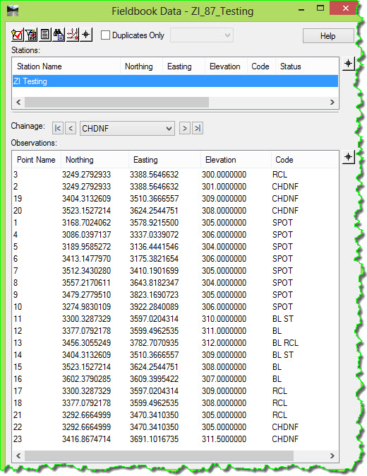
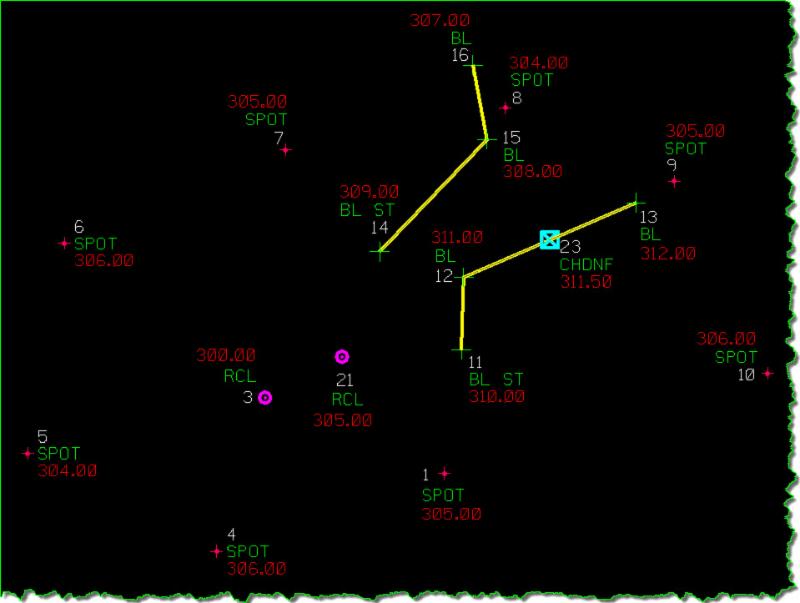
Here is the test that I did: (Don't bother reading too much into the shots themselves, this was just done as an arbitrary illustration design to examine the resulting surface).
I entered 23 total shots into an InRoads Survey field book. This sample data contains:
- Two Breaklines (with 3 shots each). [Point #'s 11-13, and 14-16]
- One of the Breakline shots, Pt #13 is 'double-coded' with BL & RCL to produce an additional Random point at the precise location of the end of the Breakline.
- Eight haphazard SPOT shots were added as Random points just to form some outer surface data for later triangulation. [Point #'s 1, 4-10]
- Two coordinate-coincident Random points [2 & 3] with varying elevations.
- Two coordinate-coincident Random points [21 & 22] with the same elevations.
- Two Random points [19 & 20] that fall precisely on a Breakline vertex with the same elevation assigned to them.
- Two Random points [17 & 28] that fall precisely on a Breakline vertex with different elevation assigned to them.
- One Random point [23] that falls directly on a Breakline, not on a vertex, with the same elevation as the interpolated Breakline elevation at that location.
 Not that it really matters here, but just for added clarity (and in case anyone cares) here is the coding that was used:
- BL = General breakline,Breakline, Included in Triangulation
- SPOT = General spot elevation,Random Point, Included in Triangulation
- RCL = Round drain, RandomPoint, Included in Triangulation
- CHDNF = Benchmark monument,Random Point, Included in Triangulation
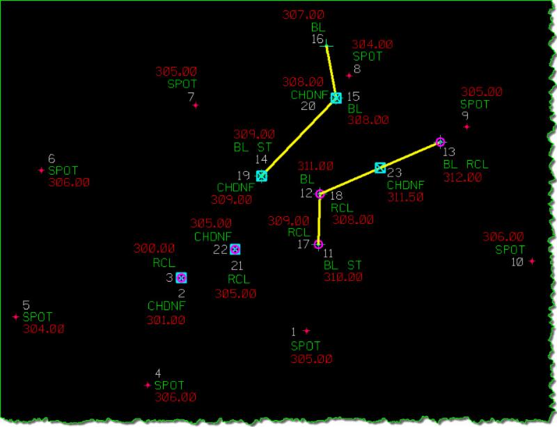
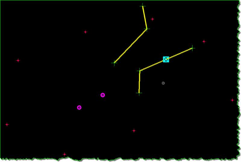
The sample data looks like this in the CAD drawing: (If you are really interested you should take a little time to correlate the previous Fieldbook snapshot, along with my sample data description, with the CAD drawing shown here. Otherwise just follow along conceptually).
Now, this data will be moved from the InRoads Survey Fieldbook into a surface DTM. By the way, this is how existing surfaces are created from traditional ground surveys. This 'export' is a very simple process that takes about 5 seconds to perform. The only reason that I did this was to be able to create a better catalog of the original data. I could have just entered this data directly into a surface model, but for reasons that will reveal themselves, you'll see that it has its drawbacks during testing.
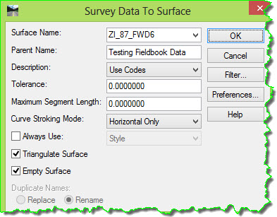
This is the tool to move the survey Fieldbook data to a Surface.
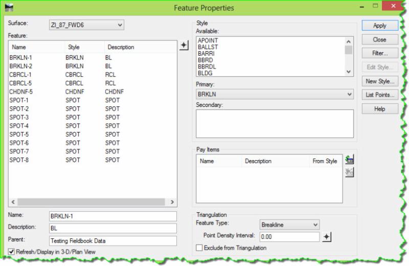
Now let's look at the resulting surface and the data that it contains. And remember that this surface was 'seeded' by all of the data that was previously shown in the survey Fieldbook. No data was held back as it was pushed into the surface.
This is the CAD display of the data from surface:
This is a comparison of the data that the fieldbook actually contains along with the data that the surface now contains.
Looking for the original 23 total shots (24 total points located) results in this:
- Two Breaklines (with 3 shots each). [Point #'s 11-13, and 14-16]
- One of the Breakline shots, Pt #13 is 'double-coded' with BL & RCL to produce an additional Randompoint at the precise location of the end of the Breakline.
- Point coded as RCL - GONE
-
Eight haphazard SPOT shots were added as Random points just to form some outer surface data for later triangulation. [Point #'s 1, 4-10]
- Two coordinate-coincident Random points [2 & 3] with varying elevations.
- Point #2 - GONE
- Two coordinate-coincident Random points [21 & 22] with the same elevations.
- Point #22 - GONE
- Two Random points [19 & 20] that fall precisely on a Breakline vertex with the same elevation assigned to them.
- Points #19 & 20 - GONE
- Two Random points [17 & 28] that fall precisely on a Breakline vertex with different elevation assigned to them.
- Points #17 & 28 - GONE
- One Random point [23] that falls directly on a Breakline, not on a vertex, with the same elevation as the interpolated Breakline elevation at that location.
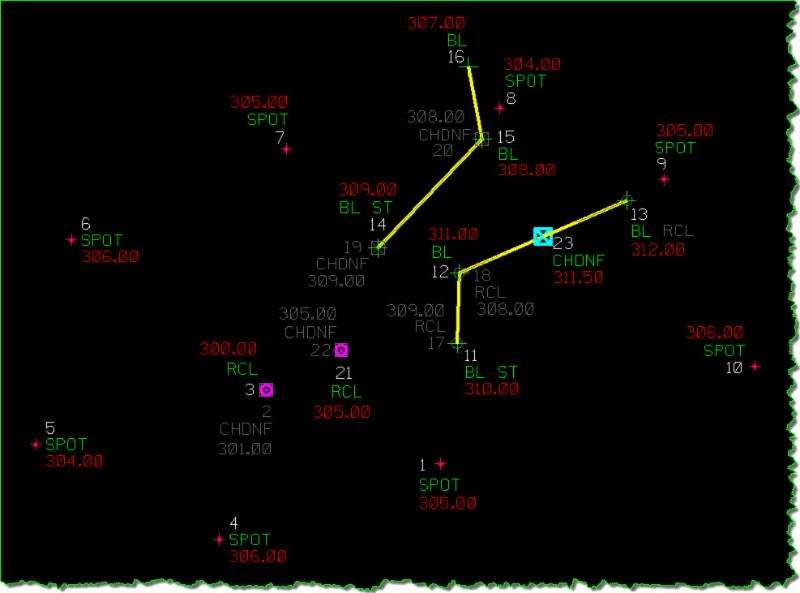
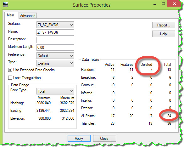
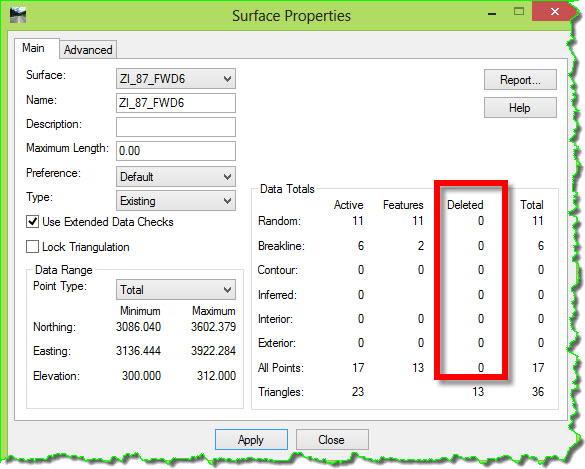
Of the 24 total points that existed in the survey Fieldbook, 17 are in the surface DTM, and 7 are gone from the surface.
Looking at the Surface Properties confirms this.
The Resolve Crossing Segments command reveals nothing about any problems because in this case, like a plot from a mob movie, the offending points have been permanently eliminated with the only trace left in the Surface Properties dialog box. And these fingerprints can be easily removed with the Compress Surface command.
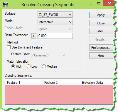
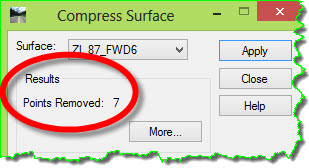
Clean as a whistle; not a trace left.
And at no time in the whole process, from Survey, to the export, to the triangulation, to the display, to Resolve Crossing Segments, the Error Log, View Crossing Segments or anywhere else was there even the slightest hint that something was amiss.
The example that was shown here was using a survey Fieldbook as the source of the 3D data. There was nothing special about this process that makes this problem unique to the export of survey data. This issue would occur just the same had I placed that Random data directly into the DTM using one of the Surface Design tools, or the SurfaceImport tools or any other method of introducing 3D data into a surface model.
(If I happen to mysteriously disappear someday, without a trace, you'll know why ; )
The reason that I used the Fieldbook was to maintain a 'database' of my 3D information. Had I not done that, each time I would have entered data into the surface, using the Place Feature command for instance, it would have disappeared as soon as I triangulated it and been lost forever (you can't recover deleted surface data). And then I would have had to reenter it to do further testing.
Okay . . . Oh how badly I wish I were done.
As an aside, I can't stress enough that you need to be very attentive to the construction and results of your surface models. Just because you plug 3D data into a surface does not mean that all is necessarily well. Call me a fanatic, I don't care because I generally do not have odd things going on with my surfaces because I'm very conscious about what I'm doing each step of the way, constantly checking my work. And if I see anything unusual, I am all over it running it down until I'm completely satisfied that I understand what's going on.
Let's look at one last oddity before I attempt to walk away from this subject.
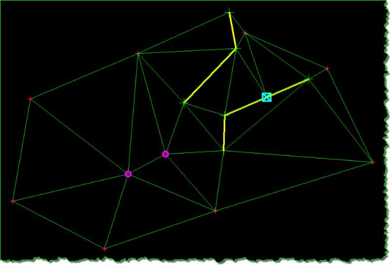
This is the resulting triangle display formed by this data.
In addition to the unannounced removal of Random point features there are other oddities that can occur when point data is coordinate-coincident with other data. And it's at this stage, regarding the cause and effect of all the possible variations in the software reactions that I begin to become a generalist and assume a posture of a skeptic. In other words, because of the amount of possible 'conflict combinations', fused with the various differences between software versions, and the untested nature of this subject, I tend to just be really alert to anything unusual.
We already know that InRoads deleted some Random points without our permission, but at least it left us some to build the surface model from, right? Now let's take a look at the connectivity of the data that remained in this surface by viewing the triangles, shading them, and rotating the view to look for any anomalies.
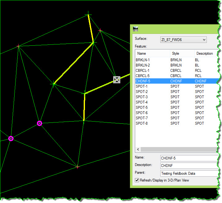
To illustrate this a little better, I'm going to take the Random point that is positioned along and on top of one of the Breaklines and change its elevation. Right now it was set to 311.50 to match the interpolated elevation along the Breakline at that exact location. So currently there isn't an elevational conflict between the Random point and the Breakline. But what would happen if there were an elevational conflict? It will be changed to 315 to illustrate something new.
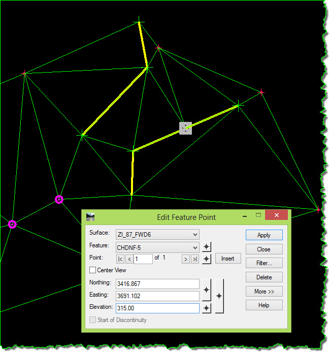
Now, with the revised elevation, the first question is - When this is triangulated it will be introducing an elevational conflict into the surface model, so what will InRoads do with it? Will it delete it? Will it 'ignore' it?
Well, how about that? It didn't delete it. So now what?
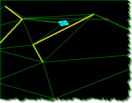
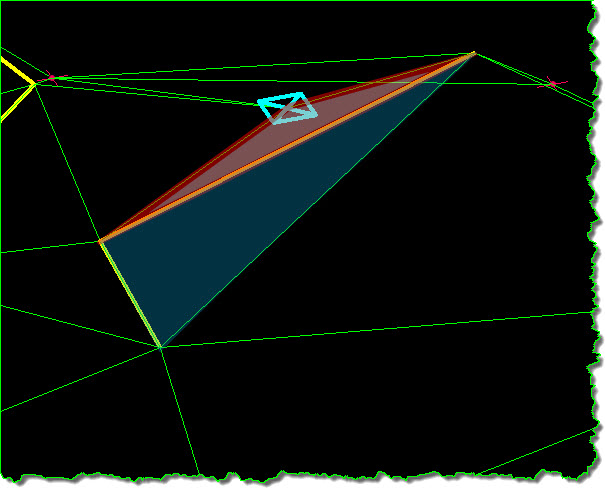
Okay, this is a test - Do you see anything odd about the formation of these triangles?
The Triangulate Surface command forms 3-sided figures (triangles) that interconnect all of the data to each other forming relationships amongst and between the data. Each 'point' of data, whether it's a single stand-aloneRandom point or one of many vertices along a Breakline, should be connected to every point surrounding it.
Notice that there is something odd about the triangles in the area of that cyan point on that breakline (remember, that point is not actually 'on' the Breakline).
Let's look at it in a rotated view with and without the 3D Feature data.
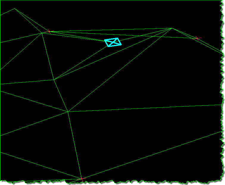
Let's look at a couple rendered and shaded views to get a different look at this.
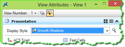
Switching the MicroStation rendering Display Style from Wireframe to Smooth Shadows or Illustration, or one of the others on the View Attributes, is commonly done to obtain a different view of the surface.
Rotating the model to get different views of that area of triangulation is more revealing.
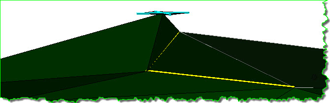
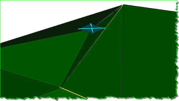
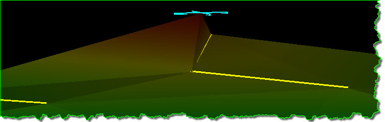
What has happened here is the Random point that fell along and on top of the Breakline was retained even though it introduced a conflicting elevation into the surface model. The retention of that particular Random point has created a triangulated surface that defies the basic rules of DTM construction, and obviously needs to be corrected.
WINDING DOWN
Here's what I've found out about how InRoads is handling duplicate points.
InRoads addresses duplicate Random features by physically removing one of the Random features from the DTM. The removal appears to occur in order of placement with the first point that is encountered retained and all subsequent conflicting points deleted from the DTM. It's as if the DTM processing identifies a coordinate location and its associated elevation and stores it, then when another point is encountered with the exact Northing / Easting the elevation is compared to it. If the elevation of this later point is different than that newly encountered random feature, it is deleted from the DTM.
Earlier in this document, all of the discussion focusing on linear Breakline data and the methodology that InRoads addresses any linear conflicts can be summed up by saying:
"When InRoads encounters conflicting 3D data in a surface it will 'ignore' something, retaining only a single elevation so that it can complete the triangle formation."
Here is the not-so-subtle difference between how the InRoads triangulation routine addresses Breakline-Breakline conflicts and Random-Random or Random- Breakline conflicts. In the case of Breakline -Breakline conflicts, something is 'ignored' in order to 'resolve' the conflict. In the case of Random-based conflicts, something is 'deleted' in order to 'resolve' the conflict. Yes, 'deleted', as in "good-bye".
Here are some of my 'thought bullets' that I've found during my testing:
- If a Random point falls on a Breakline vertex and results in a conflicting elevation value that Randompoint is then physically removed from the DTM.
- If a Random point Feature falls on a Breakline vertex that Point Feature will be deleted from the DTM, even if the Random shot does not have a conflicting elevation with the Breakline.
- Depending on the version of the software I found that the deletion of data has changed. In an earlier version of InRoads Survey, if a shot is double-coded during survey field collection, and that data is pushed to a surface model both points are retained. This is not true in the current version. In my testing with an earlier version of InRoads Survey it only deleted a feature when the point conflicts with a piece of linear data.
- When Random points are imported from graphics as a Feature group, any duplicates are weeded out at that time. One point will remain for each unique X / Y location. At this stage conflicts with Breaklines are not checked or considered. There is really no way to tell which specific points were brought in and which ones were deleted but it appears that the same logic described above is being applied. (First point taken and subsequent ones tossed out.) The only important thing to note here is that if there are multiple points at a single location the first point encountered establishes the elevation of that location.
- The rule appears to be that if a Random point is located on a Breakline vertex point then that Randompoint is deleted. If all Random points coincide with points along a Breakline then the entire Random point Feature is deleted.
- In processing (triangulating) Breakline points and Random points, any duplicate or elevationally deviantRandom points, (compared to the Breakline vertices), are deleted from the DTM.
- If the Do Not Triangulate option is turned on for that Random Feature then that data is retained.
RANDOM POINTS SUMMARY
InRoads addresses duplicate Random points by physically removing one of those points from the DTM. If aRandom point falls on a Breakline vertex and results in a conflicting elevation value that Random point is also physically removed from the DTM.
The removal appears to occur in order of placement with the first point that is encountered retained and all subsequent conflicting points deleted from the DTM. Elevation plays a very small role in the addressing of these duplicate Random points. If a point falls on a Breakline that point will be deleted from the DTM even if the Random shot does not have a conflicting elevation with the breakline.
In an earlier version of the InRoads software if two Random points were directly on top of one another and had the same elevation then the last one checked was retained. It was as if the DTM processing identified a coordinate location and its elevation and stores it, then when another point was encountered with the exact N/E the elevation was compared to it. If the elevation of this later point was different, then that random feature was deleted from the DTM, but if the elevations were the same, it (the second point) was used and the earlier one was deleted from the DTM. In the current version of the software it seems to always retain the first point it encounters and deletes any subsequent points in the surface, regardless of the elevational relationship.
I think the biggest issue I have with this whole Random point removal is that it is not reported on during theTriangulate Surface processing, or anywhere else, so that the user is made aware of the lost data. And believe it or not, I logged this problem back in October 2001 while I was working at Bentley Systems, and it was filed as CR CV37734.
So the cat is out of the bag. What do you do now? Stay alert. The software is a tool, not a co-worker doing your job for you. Using software requires you to be smarter, not more complacent. Check, check, check your work and let others check it too.
CLOSURE
Okay is this subject exhausted? No, not in my mind, but I'm done for now. Although I still have these items on my hit list:
1) How does InRoads triangulation address the conflict created by 2 breaklines when one starts where another ends, and the elevations are different? I've always seen this as a Mismatched Elevation scenario. My initial testing done a while back showed that it is taking the lower elevation and ignoring the higher one, but it's not reporting on this nor is this conflict area being identified when using the View Crossing Segments command.
2) How does the latest version of InRoads address partially overlapping breaklines? Earlier version of InRoads would not recognize partial overlapping breaklines. The overlapping had to be a complete duplicate in order for InRoads to acknowledge it in both commands and the reporting.
3) Is it true that the ResultsError Log report lists the problematic areas starting from the lower left to the upper right? (Increasing X & Y values.)
4) What's the deal with UntriangulatableData!!! And how should it be addressed? I know what I do to address this, but what is really going on here?
That is it!! . . . What a road this has been. I'm really done!!
Coming next . . . something new (and hopefully shorter for me and more digestible for you) - ZI Issue 87: Contour Smoothing
 Mark knows his stuff; he made learning fun and easy. He was very structured and good at explaining material. He created a comfortable atmosphere for learning and has great knowledge of the InRoads Software. Without a doubt Mark was Excellent.


