Although the bulk of users, along with my personal workload, are still mainly on InRoads SS2, I've of course been dabbling with the next generation of InRoads tools that are built on the OpenRoads platform (SS3 / SS4+). With that in mind, I decided to issue this little-known technical nugget about InRoads SS2. I selected this because in the next evolution of InRoads, project information like horizontal alignments, vertical alignments, surface layout, and roadway models have the capability to be dynamically 'ruled' together. That means if you revised your horizontal centerline, the related project data could dynamically change the entire way through to the final model and cross sections.
With that said, there are some little known dynamic relationships that are built into the current SS2 version of InRoads that most people are unaware of, and understanding this current functionality will give you a leg up when the next generation of InRoads is complete, and it ends up on your computer.
First, let me set the stage - You've laid out a horizontal alignment, created a Profile, and laid out your vertical.
Now you want to modify the Horizontal alignment.
The question now becomes - what are the implications of the horizontal edit 'downstream' on the work already done?
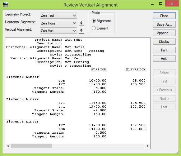
Here's our starting point for illustration purposes:
- There is a simple horizontal alignment without any horizontal curves that has a starting station of 10+00 and an ending station of 14+00.

- It has a vertical alignment with nice round numbers that spans the entire stretch of the horizontal, also without curves.

At this stage, you should understand a couple things (please let me know if I need to clarify any of these items because they are the foundation underneath this topic, and the principal groundwork for moving forward):
- If you layout your Horizontal Alignment you can edit it any time after that with no ramifications
- If you layout your Horizontal Alignment and your Vertical Alignment ... you cannot just go back and edit your horizontal without considering the implications of the horizontal changes to your vertical design
- By default, the Vertical Alignment is stored as 'Station-Elevation' relative to the Horizontal alignment
- If you add curves to a Horizontal Alignment that didn't have curves, that alignment will be shorter. This will throw any 'child' Vertical Alignments belonging to it out of sync
- If you revise curves on a Horizontal Alignment that already had curves, that alignment length will be either longer or shorter depending on whether the curve radius gets smaller or larger
- No matter what horizontal revisions are done to a Horizontal Alignment, if there is already a Vertical Alignment associated with it, then those two alignments will go out of sync
- Another ramification of a horizontal edit is that the Profile ground line will no longer accurately represent the ground under that horizontal and will need to be either updated, or recreated.
An example of an edit that illustrates the vertical "Station-Elevation" storing methodology would be if you changed the starting station of your horizontal ... and not your vertical. If you constructed your H & V, and your geometry initially started at 0+00, and then you later changed the starting station to 10+00 on the horizontal only, the vertical will still be stored at location 0+00 for the first point. Options that address this issue are visible on the Stationing dialog box in the Vertical and Superelevation Alignments section.

By default, the Vertical Alignment is tied to the Horizontal Alignment based on the horizontal stationing during its layout; however, this 'tie' is not "dynamic". If you change the horizontal layout, the vertical layout doesn't automatically change and update. This is all super-easy to illustrate ... but I'm being a bit lazy right now. Plus this is a good opportunity for you to get some hands-on and confirm for yourselves that what I'm saying is true by doing a little testing.
Look at this illustration.
Notice that if I modify the horizontal identified earlier (by adding curves that makes the overall alignment shorter), that this is directly observable when the alignment is stationed. In this case, the end station changes from 14+00.00 to 13+91.54, so it was shortened by over eight feet.

Original alignment without the curves:

Revised alignment with the curves added:

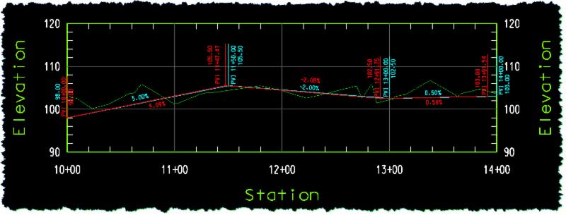
With this horizontal change, what is happening with the vertical alignment that has been created under this horizontal? Before that question is answered let's look at what happened to the profile by creating a new profile and overlaying it on top of the profile created by the original alignment.
Notice the difference in the existing ground line. The green is the 'new' ground line related to the modified horizontal. The grey line was the original ground line under the initial horizontal alignment.

What about the vertical?
The horizontal alignment is now 1,391.54 feet long.

While the vertical is still 1,400 feet long, over 8' longer.
At this point, some amount of vertical alignment editing would have to be done to at least make sure that the stationing at the end of the vertical alignment matches the end of the horizontal alignment. This can become much more complicated if there are strategic points on the vertical that are tied to specific vertical locations like grade crossing or other specific vertical tie points. In addition to the fact that since the existing ground line can change, sometimes dramatically, your vertical design may have to be revisited to minimize cut / fill, or provide clearances with existing or proposed utilities like in this example here:

Now the reveal:
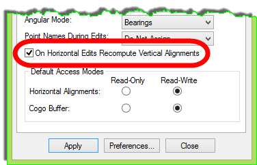
If you go to File > Project Options, on the Geometry tab, you'll see a setting called On Horizontal Edits Recompute Vertical Alignments. This was added in the V8i version of InRoads as a solution to a Horizontal Alignment edit done after the Vertical Alignment had been laid out. More than likely this toggle is off since most users not only don't know what it is, they probably don't even know that it exists at all.
This setting activates what is called "Vertical Alignment Healing". Pretty cool name, huh? There is a little introductory write-up in the InRoads Help file on it that you should read ... so I don't have to repeat it here ; ) Basically what this does is associates a Northing / Easting coordinate to each of the Vertical PIs. So that when a horizontal alignment is edited, the 'companion' Vertical is recomputed in an attempt to tie them together and modify both the H & V at the same time.
At this point, I'll make this additional statement, this method was really intended for geometry work that uses, or is focused on, the PI or "Curve Set" method of layout. This is because that tool set (or that type of layout logic) is based on a continuous or contiguous alignment (no gaps or discontinuities). When using the "Element" tools for layout, this method isn't employed as much because other techniques and workflows can be used with these tools to address the same issue. With that said, this method can be used on any alignment, but in some cases, it's just not as applicable.
The Help file "Workflow" says that you have to toggle this switch on before you create your Geometry Project, but you don't have to. I've found that you can toggle it on or off anytime you want to use this technique ... just prior to your horizontal editing or revisions. It appears to me that the N / E coordinates are assigned to the vertical at the time of the horizontal editing ... if that toggle is on.
Let's look at the differences in the horizontal and vertical alignments before and after some horizontal editing while using Vertical Alignment Healing. As an illustration, this will be done by using the alignment mentioned earlier, and adding two 100' curves to show the difference.
Here's the original horizontal and vertical alignment:


Here it is after the horizontal revision: (with 2 - 100' radius horizontal curves added, but no editing done on the original vertical alignment)


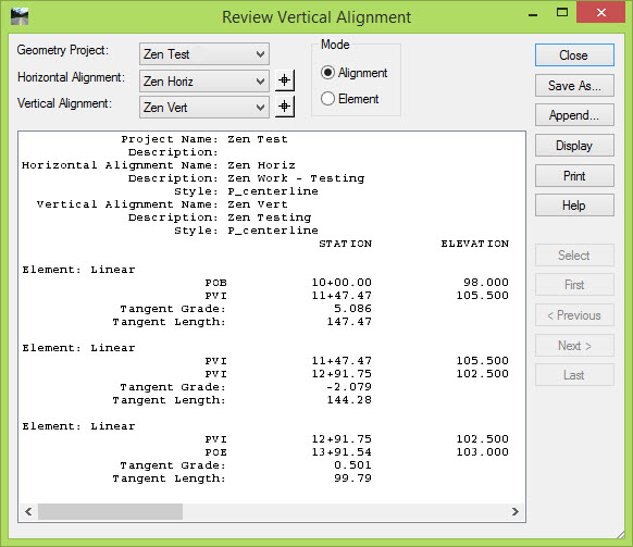
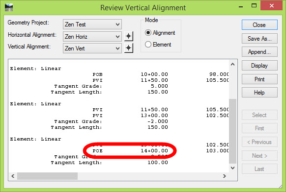
Notice the POE (Point of Ending) for both the horizontal and vertical alignments are identical (13+91.54), even though they both previously ended at 14+00, and only the horizontal was modified.
I hope I'm not losing you, but if you create a profile prior to the edit, and then after the edit, you'll see something like this: (The cyan is the Vertical alignment before the horizontal edit; the red is the vertical alignment after the horizontal edit). Notice the station changes and subtle grade changes ... but the elevations are held constant before and after.
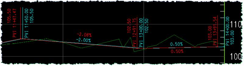
Of course the drawback to this technique is the odd station and grades that you will probably end up with, but you can just do whatever vertical editing as needed to clean up those values. And on a small alignment like this the savings isn't that large, but on a very long alignment this could be a strong technique with significant pay-off.
There are other aspects of this that need to be considered such as:
- If the Horizontal edits cause the alignment to lengthen, then the Profile may have to be recreated or else the vertical won't fit
- The ground line from any DTMs on the profile will need to be revised or updated because they were originally displayed as they tracked along the original horizontal. By revising the horizontal, the ground line shown on the previous profile is no longer correct.
To wrap up this topic; focus on the horizontal ... get it right, and then work the vertical. If something changes on the horizontal then work that issue out ... but always remember to verify and validate the vertical. It's all about remembering that the Vertical Alignment is a 'child' of the Horizontal Alignment. If you mess with the 'Parent' Horizontal, then you had better verify that the work hasn't adversely influenced the 'child' vertical ... or verticals. Also keep in mind that the Profile window should also be considered a 'child' of the Horizontal Alignment, so if the horizontal is revised, it may have implications on the profile itself.
I hope you learned something valuable!!
As always, let me know if you have any questions!!
And lastly, for now, I know that as I answer questions like this, I make a lot of assumptions that you know how to do things like create Profiles, view Vertical Annotation and even display multiple vertical alignment annotations on a single profile window. If I lost you on a particular step, please let me know, but this should show you that in order to really use InRoads effectively and make it execute your wishes as you solve design problems or develop the project work, you really have to have a strong understanding of its tools and capabilities. InRoads is powerful ... but you have to learn how to wield that power.


 There is only one Mark Ditko. We need him for future training. I think he could help iron out some of the problems in the department.


